The cam came with a low power 5V regulator, so it could be used with 9-12V, cut away and throw out.
The idea about this page is to inform about what I have purchased, where and how much,
how it perform and what kind of modifications I will/have made to it..
Please also see the Video OSD, On Screen Display page and see bottom of this page for VIDEO clips !
and 2.4GHz antennas and their measurements
and Filter designs and measurements for GPS
and LNA 2424 from RF Bay pictures and tech info
and Install gear into STICK and other pictures from preparing for the Aspach tour 2007 - Video and Pictures from Aspach2007
Wireless equipment purchased from Black Widow A/V
They take paypal, answer emails, are fast and easy to deal with.
I ordered this:
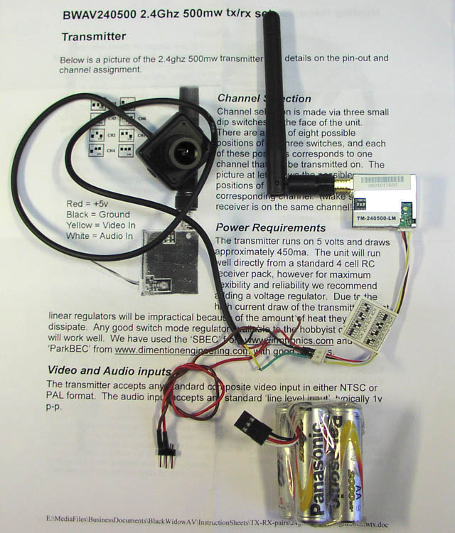
KX131 CASED 5V Color CCD Camera 70 degree lens PAL, KX131CASED-70-PAL $149.00 USD
2.4ghz 500mw tx/rx set,TD240500TXRX $174.00 USD
International Shipping Charge $19.00 USD , plus USD Shipping: $6.00 USD, (funny some postage again ?)
Cart Total: $348.00 USD, PLUS 25% extra on top of all this !! due to local import tax when parcel arrived in Danish custom service.
Total payed in DKR = 2560
By the way: I later found out another company called rangevideo also sells exactly the same good stuff, but for a much lower price, check it out !
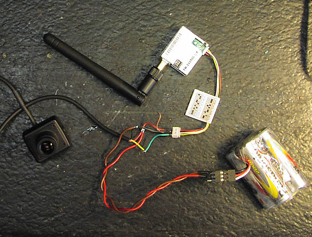
The cam came with a low power 5V regulator, so it could be used with 9-12V, cut away and throw out.
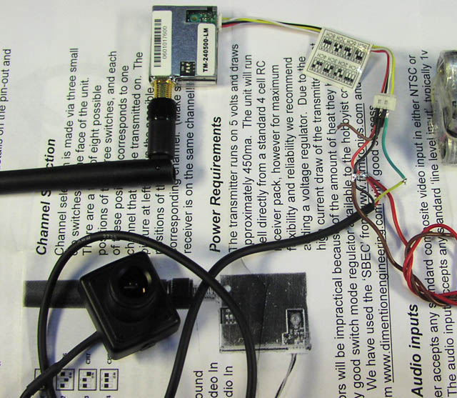
Connect cam and tx as explained in the good doc sheet.
CAM uses 200mA and TX uses 500mA both at 5.0V DC, so we need a switchmode step down regulator (more about this later)
Be warned: this TX unit is quite powerfull so it gets extreamly hot, too hot to sit inside not moving, it is designed to be used on a flying plane,
mounted so wind will cool it. Another alternative is to mount a much bigger heat sink, adding more weight.
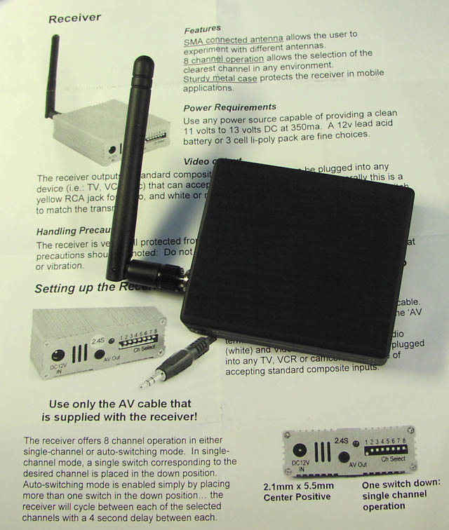
The RX unit run on 11-13V DC and uses 300mA so if your voltage supply is over 11V, be aware it will run hot.
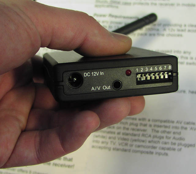
Standard jack and DC plug are used, channel select with DIP switch.
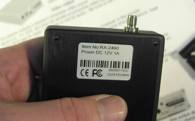
Antenna connector is SMA, and both antennas are included.
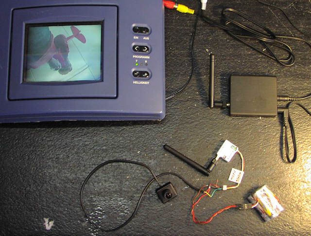
This old LCD video PAL screen runs on 12V and uses 750mA
so RX and LCD uses about 1A together, I need to take this into consideration later.
it was fast and easy to mock it all up for test.
Picture quality is razor sharp, ultra fast gain control with no clipping or freaking out with sharp light,
like often seen on cheap shitty cmos cams.
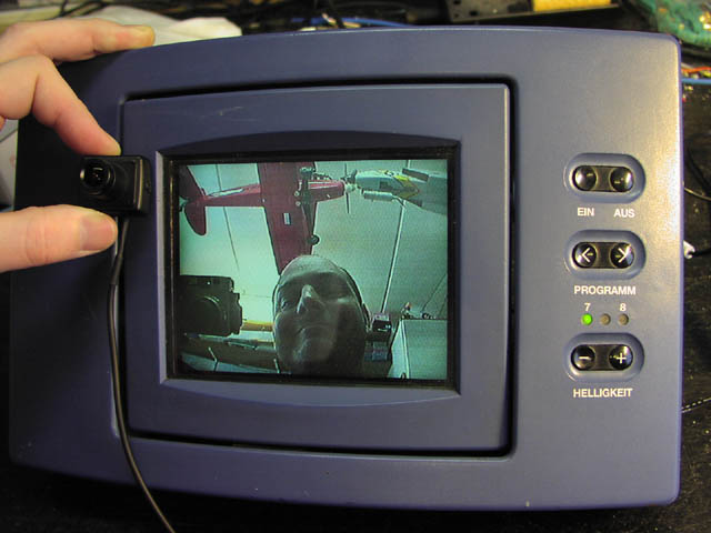
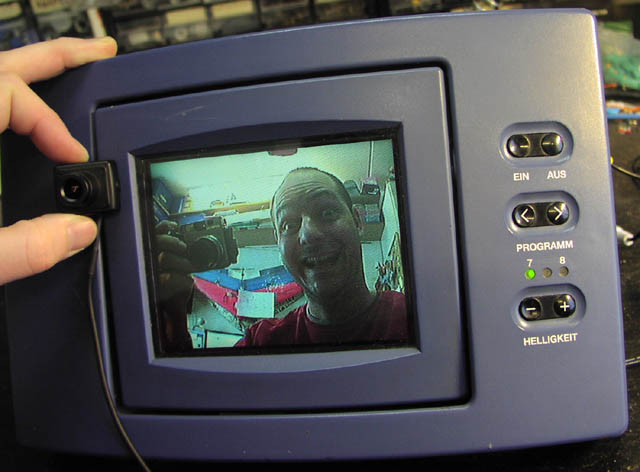
see I am happy, the first test showed plenty of range even indoor.
next step, fly test... later...
Measurements:
TX, RF power measured at center carrier, with no video and no audio modulation:
28dBm 630mW at 5.0V - 27dBm 500mW at 4.5V - 26dBm 400mW at 4.0V - 24dBm 250mW at 3.5V - 23dBm 200mW at 3.3V
TX, current consumption 400-500mA at 5V, depending on SWR, 450mA at 20dB rtn loss
TX, spurs: 4.7GHz -18dBm, 7.1GHz -31dBm, no futher spurs found up to 22GHz
CH1 2410 MHz, CH2 2430 MHz, CH3 2450 MHz, CH4 2470 MHz, CH5 2370 MHz, CH6 2390 MHz, CH7 2490 MHz, CH8 2510 MHz
RX, sensitivity = -97dbm measured with Agilent E4438C 3MHz dev 100kHz sine (-91dBm with TV signals)
RX, current consumption 300mA at 12V
Signal chain attenuation possible = -120dB at weak noise (comment: not easy to measure due to un-tight components)
Audio Frequency response, 150Hz to 7Khz -3dB, usable from 50Hz to 20Khz
Audio conversion gain 6 times, 1vP input to TX, generates 6vP at the RX output, inverted
Video Frequency response, 1Khz to 4.6MHz -3dB, 4.0MHz=weak peak, no conversion gain and no invert.
----------------------------------
Modifications:
Receiver box heat problem:

The RX box inside reveals a standard sat rx unit, two linear voltage regulators, 9V and 5V
The microcontroller board for channel select
The temperature problem came from the two regulators, so to longen their lifetime, we must cool them down.
Adding two 10x11x3mm aluminum bricks using epoxy on the PCB side, and heat compound on the other side,
will help this allot, now the regulators transfer their heat much better to the case.
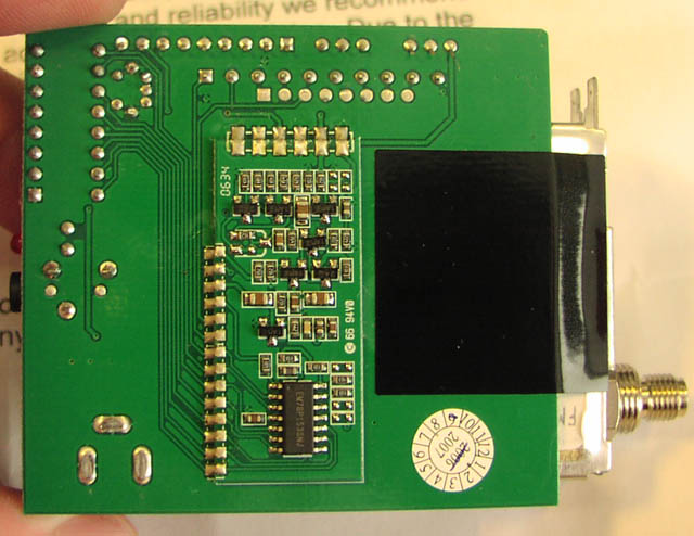
TX module, heat sink improvement:
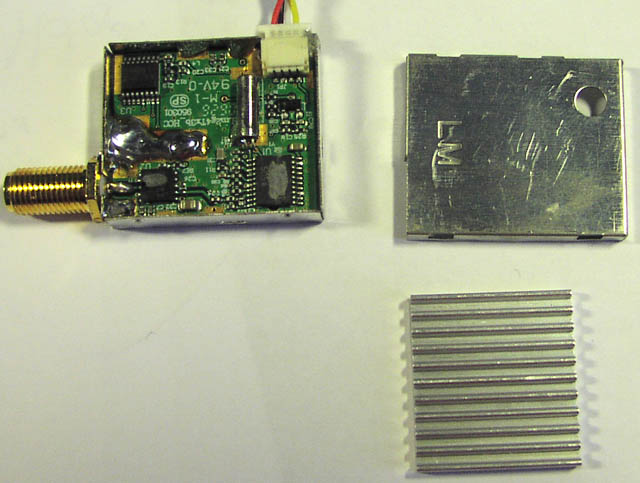
The tx module parts, lit and heat sink was attached to the TOP side with double
sided tape, first fault !
The transmitter uses 500mA at 5V so it is clear such a little box will get hot,
I had a problem with the transmitter chip overheating after a few minutes,
I could see the input current suddenly dropping 200mA, so I was very worried
about killing something way too soon. Here is what I discovered.
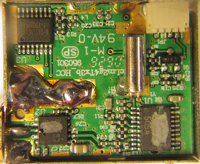
The little brass heat transfer block they have glued to the bottom of the pcb
with double sided tape !! was 2.0mm thick, so it did not touch the metal bottom
plate !
it should have been 2.4mm for this trick to be working ! and double sided tape
is not really that good to transfer heat.
funny the dip switch have 4 switches, only 3 of them are normally access able.
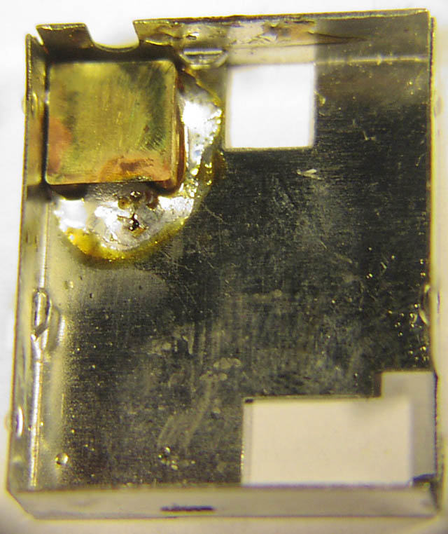
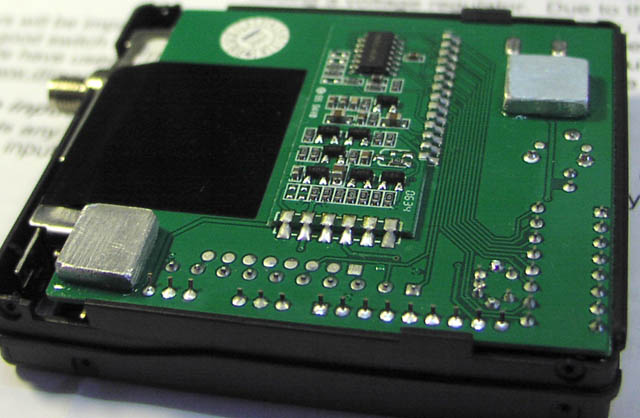
I tinned both the brass brick and the BOTTOM case, soldered it straight, and
checked the height to be 2.4mm, now I have got a match.
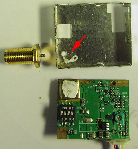
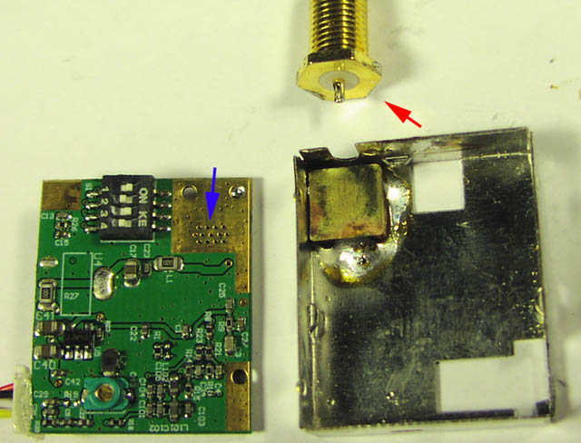
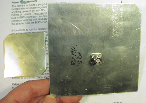
Originally the SMA connector was not soldered properly to the case, there was a
minor risk of braking if off, the red arrow indicate the back side,
I tinned this side and the outside of the case, the soldered with plenty of tin,
not it's much more strong, and can transfer heat much better.
The blue arrow indicate the back side of the hot power amplifier, here I used
heat transfer compound.
I was carefull to press with a screwdriver on the board, while soldering, so the
board will touch the brass block as good as possible.
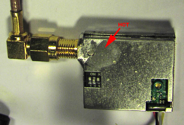
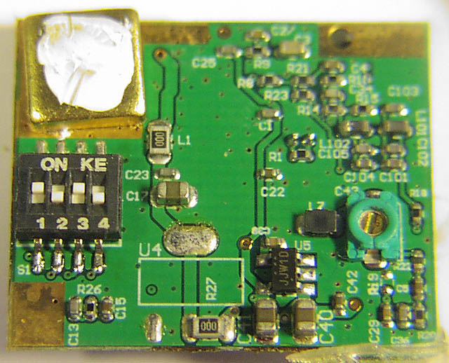
Here at THIS side, the red arrow points to the hot spot. This is where the heat
sink should have been mounted,
now the input current is stable ! and the hot chip will live longer I hope.


Finally I added a small aluminium plate, 1.5mm thick to the hot TOP side, and
mounted the heat sink where it will cool the best.

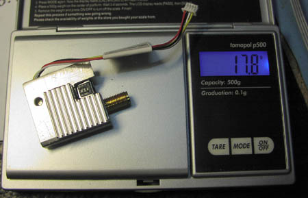
OK I have added about 5gr to the transmitter, but now it can transmit continuous
without temperature overloading.
Receiving Antenna improvement:
Normal quarter wave antennas supplied with this video link equipment,
have a gain of 0dB when BOTH pointing up !
If one of them are horizontal and the other vertical the attenuation will be
-24dB extra added to the link.
To solve this the receiver antenna is changed a circular polarized giving a -3dB
constant attenuation no matter what rotation of the transmitter antenna.
A super good homebrew guide was found here:
http://www.rc-cam.com/gp_patch.htm
Here is a few pictures of my version, I have improved it slightly, bottom plate
2mm alu and made 4 x 2mm threads for 2mm screws,
and I am using a really good quality SMA connector:
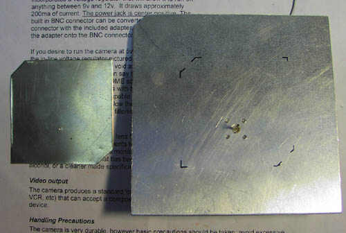
The parts.

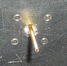
SMA connector: Note the length of the screws how exact they match, also the
center pin is long, perfect for this project.

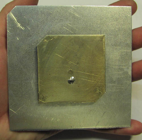
The shape and size of this kind of antenna is really special, the reason is the
polarization of the radio waves.

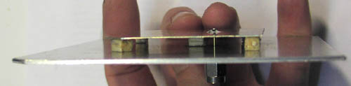
The air gab is changed to 4mm, spaced with 5 pieces of balsa wood.
and the Patch size changed to 54.1 x 54.1 mm see here why:
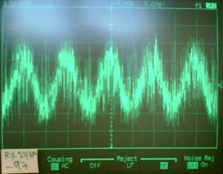
Return Loss measurement here the original unmodified:
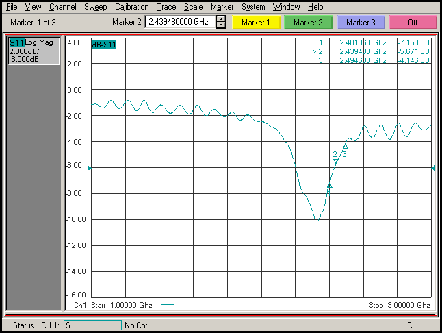
Here the original design feed patch was 56x56 and 5mm height from bottom plate.
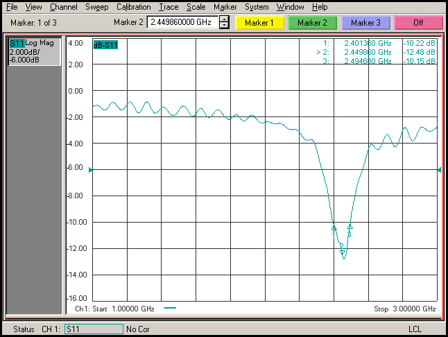
Here the changed feed patch is 54.1 x 54.1 mm and 4mm height from bottom plate.
I did not change the bottom plate it is 107.4 x 107.4 mm.
Return loss of 5dB equals 1.65dB reflection power loss, equals 68% of the power is used. (or 32% wasted)
Return loss of 12dB equals 0.28dB reflection power loss, equals 94% of the power is used.
1.6dB is the same as changing your transmitter from 500mW to 700mW
simply by uptimizing the antenna for free, nice nice.
The first on ground test results was impressive !
Much less holes in the signal with this Patch ! and much more range, Super !
Switchmode power supply for Camera and Transmitter in plane
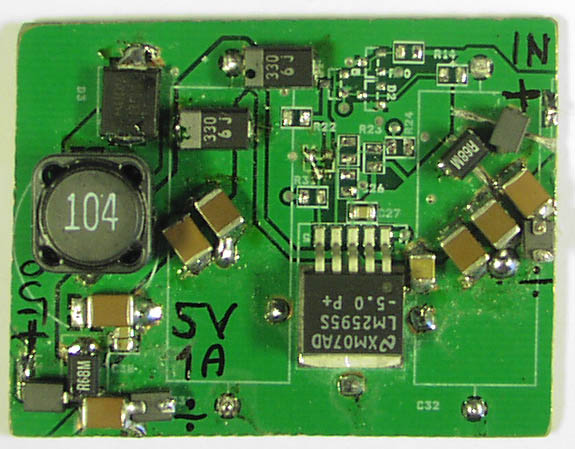
As explained erlier on this page, the camera and transmitter consume alot of
current, using lineary regulators will generate heat,
and waste battery, I will fly on 3 x lipo or 2 x lipo, so this switchmode is
perfect, it will generate a fine stable 5.0V at 1A
with an input from 6V to 25V at impressive low loss, the printed circuit board
was cut out from some old electronics I found,
I have added extra filtering on the input and output, to avoid problems with
35MHz RC radio receiver and GPS receiver later to be added with OSD.
Thomas Scherrer OZ2CPU January/February/August 2007