Wattmeter Counter Output
This ERA amp is mounted on the back side of the wattmeter input card.
You need to make a 10 x 10 mm pcb for this amp.
All parts are SMD ! the 51R is soldered on the wattmeter input card R16 PAD.
The output has about +10 dB attenuation compared to the wattmeter input connector.
Here is the double sided PCB layout. Width 22.5 mm x Height 17.5 mm and 1.6 mm thick glassfiber board.
Bottom side is all cobber, use 1 mm pins to connect to the bottom layer at the places shovn as a via.
You can download the PCB layout here: HI RES GIF
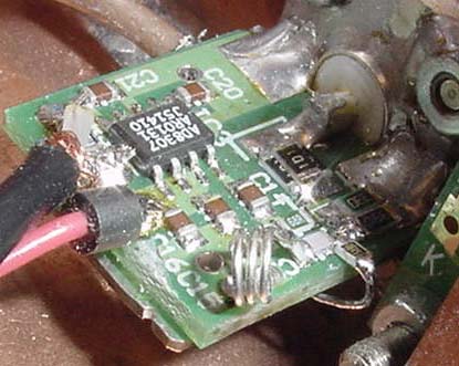
The ERA board is small and placed under the input board,
note the 51R input resistor is visible, and the output coax.
Here is the wattmeter block schematic with the ERA amp
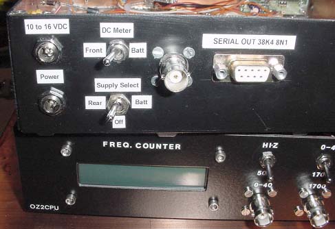
The rear panel has now been modified with a new BNC output connector
The counter output has fine useable gain up to 1.3 GHz
Freq Counter DFD4
This is a PIC16C71 design made by: Neil AADE.COMGet a DFD4 KIT from him, it is really good and cheap !
Here is my modifications to improve it.
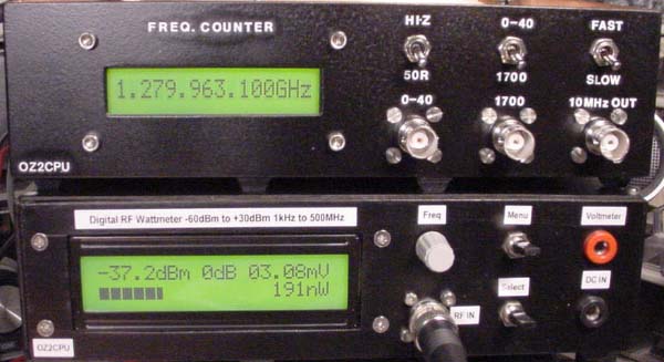
Here is my counter and wattmeter connected,
Now I can measure freq and signal power at the same time
Here is the counter simplified block schematic
To make the DFD4 counter more acurate and stable, I have improved to 10 Mhz clock circuit.
This circuit uses a digital multiplexer to select internal TCXO or externel clock.
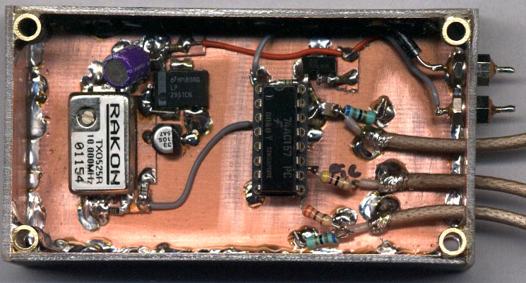
Here a photo of the 10Mhz TCXO and clock selector.
The DFD4 schematic. Modified to benchtop counter, with external clock input.
You can use eny 16 x 1 alpha LCD type, the DFD4 kit from AADE is complete with LCD, PIC, PCB and parts.
Here is the 0 to 50 Mhz input, modified and improved,
the original input circuit will oscillate with low input signal and low freq.
This input circuit with 4 BSX 89 have a sensitivity of about -60 to -50 dBm !
It can also handle input signals up to +20 dBm with no problems !
The Hi-Z / 50 R input impedance resistor and switch is simply connected in parallel with this input.
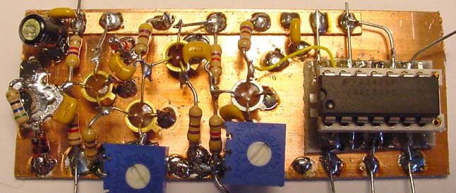
Here is a picture of the 0 to 50 Mhz input circuit before mounting inside the box, close to the input BNC
The prescaler input schematic will come here soon.
This page is underconstruction, more info and pictures will come soon !!
![]()