 www.webx.dk Start page
 OZ2CPU Radioamateur mainpage
 Homemade electronics Stuff old and new
 Digital Wattmeter Assembly
www.webx.dk Start page
OZ2CPU Radioamateur mainpage
Homemade electronics Stuff old and new
Digital Wattmeter Assembly
 Digital Wattmeter Assembly Instructions
Vis Dansk Side
Digital Wattmeter Assembly Instructions
Vis Dansk Side
To get optimal performance of this instrument,
it is important that this description if followed carefully.
This construction is made using SMD, surface mount devices,
This is because small components is best to handle high frequencies.
Click here to read more about SMD components
Two input printed circuit boards are delivered, only use and mount one.
The spare input board is for a future idea, to measure SWR.

How to solder SMD:
If you are soldering with your right hand, first add a small amount of tin on the right pad.
Place carefully the component using a pincet with your left hand,
solder the right side while holding the component just perfect straight.
Now simply solder the left pad and left side of the component,
You can see on the pictures that I have used too much tin..

Same procedure is used on all the other SMD components.
Place tin on the right pad, and place tin on the most right side of the resonator first
To solder the AD8307: place tin the pad number 3 first, then hold the IC the right place when warming fast on pin 3
When it is perfect placed, just solder the rest of the pins.
Input circuit:
Resistor R15 is made with 3 paralled 100R SMD size 1206.
The first two are mounted next to each other side by side,
The last one is mounted on top of the first two.

Resistor R16 is made with a 33R and a 39R SMD size 1206 in parallel, side by side.

R14 that is 47R is standing up from the pad where C13 (8p2) is mounted. the other end of R14 is connected to L1,
It is a good idea to solder the small coil to the ground via first, then the other end is bended to reach R14
First now solder to R14, else it is easy to brake R14
L1 is 0.5 mm tinned cobber wire, 3 turns arround a M3 drill. Vindings as close as possible without shorting

Since it is not easy to see the text on the small inputboard,
the black text is added on this picture..
The input board needs to be mounted on the input connector, it can be a BNC, N or SMA, I like BNC.
Some BNC connectors have a small teflon isolation coming 3-4 mm out of the connectors solder side,
Cut this isolation away, and cut the center pin so that it is about 2mm long.
First check that it is possible to solder on the rear side of the BNC, if not scratch it with a tool so that soldering is possible.
Now mount the input board, dont be stingy with the tin, solder it all the way also under the board

If the PIC16F876 is mounted using a socket, use a good type. Else to be sure of good connection solder it in the main board,
The 16 connections to the LCD display, can be done using a socket or wire.
The main board is mounted on the rear side of the LCD, using two stand-off about 10 mm long or what ever you have.
Remember to place isolation under the top nut to avoid shorting positive supply.

The rotary encoder seen from rear side, with text up, connect A & B to main board point A & B.
The 7805 regulator can be hot, either bend it down to the case and secure it using a M3 screw
or mount a small heat sink on it, a small click on type is ok
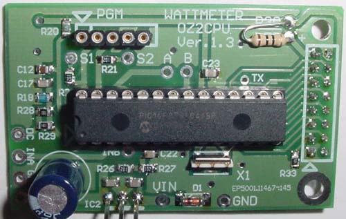
Here is the mainboard assembled and ready for the display.

My main board seen from bottom side, note the socket for the display,
then it is easy for me to dis-assemble it, if I need to make modifications.

Use a small shilded wire for the signal-connection from the Input board to the main board.
Testing:
Before mounting the PIC, and before the input board is connected,
you need to verify that the 7805 regulator is ok.
supply the board with 10 to 16 volts, check for +5 V at the pad for the input board.
check for +2.50 volts at IC1, pin 5.
check +5 V on IC1 pin 1,
Check for green light in the display
Power off.. Mount the PIC.. Power on.. Now you will see the display writing the RF powermeter
Touch with a finger the input A terminal, this will give a reaction on the display.
Double check all the solderings on the AD8307 and the input board,
Connect it to the main board, and check that current consumption in under 200mA.
If you do not have an RF test generator to calibrate and test with,
Put a normal resistor pin in the BNC input plug, and transmit with your VHF, UHF or what ever you have handy
The closer you take your handy, while transmitting, the bigger readings og the wattmeter,
Now it is tested and found OK, contact one of your local HAMS that have a good working generator,
then you can calibrate your new digital wattmeter to measure good and accurate in your own shack.
Calibrating is done by applying 0 dBm to the input terminal.
Then select the corresponding band memory, using the encoder dial
Then press menu, choose Calibrate 0 dBm and press the select button,
now the 0 dBm signal strenght is saved in the meter, from now on it will measure within +/- 0.5 dB on that freq band
This is repeated for all the other bands you need, there are 5 band memories in total, called LF, HF, VHF, UHF and SHF

Here is the display size, the hardest part of this home construction is to make the box and the big square hole for the display
There is an Construction Competition it is just for fun, plaese e-mail me a JPEG picture of your wattmeter when you are done.
please name the JPG file your call sign or name if you are not a HAM amateur.
![]()