 www.webx.dk Start page
 OZ2CPU Radioamateur mainpage
 Homemade electronics Stuff old and new
 Homemade Nixie Clock 1x6 Mux
 Here is my own private little Nixie Tube Collection
www.webx.dk Start page
OZ2CPU Radioamateur mainpage
Homemade electronics Stuff old and new
Homemade Nixie Clock 1x6 Mux
Here is my own private little Nixie Tube Collection
Since I was a kid I have loved the glow of Neon Nixie tubes.
In 2002 it was time to construct a homemade clock !.
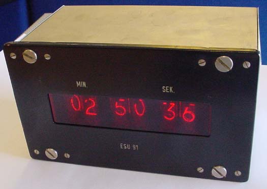
It's not easy to take a picture of something that is black
A Nixie Clock as a kit for sale Claus Urbach web page
That's me in the reflection :-)
Download Schematic in PDF format
Construction ideas:
Hours, Minuttes, and Seconds shown at the same time, using 6 Nixie tubes.
Display is Multiplexed using NPN transistors to drive all cathodes,
PNP transistors is used to drive all the anodes.
The clock logic and multiplexing is done using a PIC16F876 microcontroller with FLASH memory.
Programming is done i C using HI-Tech Compiler and MPLAP and homemade AN586 type of programmer.
Download PIC16F876 HEX file:
50Hz Negative Multiplex Pulse, 24hr mode This version fits my schematic
60Hz Negative Multiplex Pulse, 24hr mode This version fits my schematic
50Hz Positive Multiplex Pulse, 24hr mode Use this version if your Anode driver is NPN - PNP
60Hz Positive Multiplex Pulse, 24hr mode Use this version if your Anode driver is NPN - PNP
About the software:
The UP/DIMM button changes the 4 dim levels when clock is in normal RUN MODE.
The UP/DIMM button add one to the highlighted hr or min, when in SET MODE
The SET/RUN mode button enter SET MODE when pressed first time, sec is reset to zero zero.
then HR lights up, MIN and SEC is dimmed for easy indication that it is HR that is adjusted.
One more click on the SET/RUN button, changes to MIN, now HR and SEC are dimmed.
When pressing SET/RUN the last time, the clock starts to run..
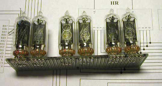
Here are my 6 Nixie tubes soldered to a vero-board.
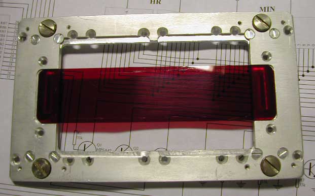
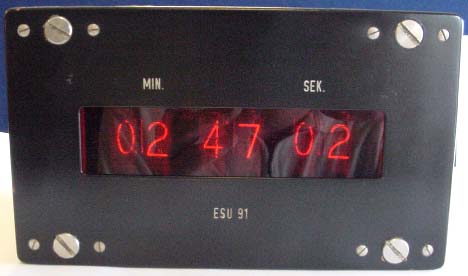
Here is the front plate from an old Lyrec tape recorder external display (1960),
The original Lyrec display used 4 ZM1000 tubes.
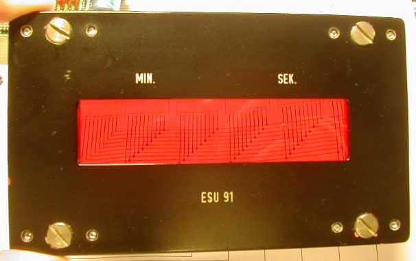
Here is the complete front.
The original MIN and SEC text does not make any sence now,
but is left there to keep the original look.
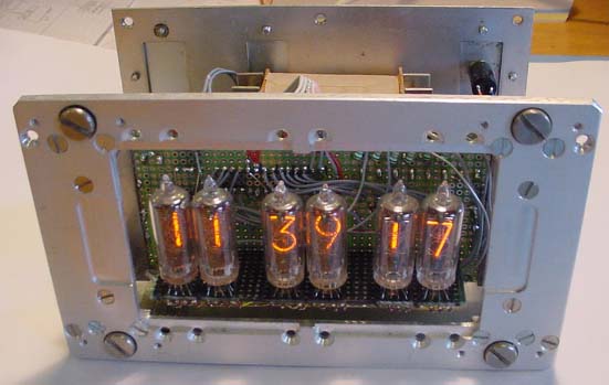
The vero board with the 6 tubes, is soldered in exactly the right place.
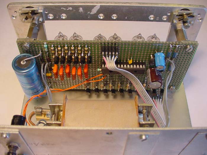
See how good it looks inside.
The programming 5 pin socket is fed to another connector.
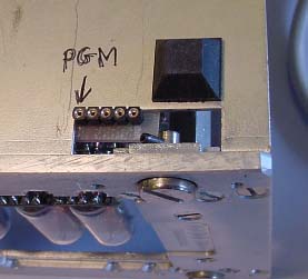
Now I can update the PIC software from outside, really smart.
About driving my PNP transistors via capacitors:
Print out the schematic, then read here:
The 6 port B outputs are always programmed as outputs, They are 1 (hi) most of the time,
The capacitor holds about 200 volts constantly across it.
Now pulling one port B pin low, the voltage on both sides of the cap will go 5 volt lower.
Then the 33 K resistor limits the base current to a safe operating level, and turn the PNP on.
After 0.5 mS the port B pin will go high again, and the PNP will go off again, now zero volts on the nixie anode.
Display update speed: 0.5mS x 6 digits = 3mS that is about 300 times / sec.
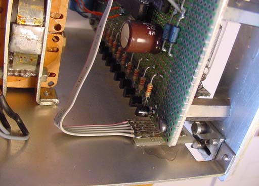
The Power supply is a small old tube-gear transformer with these in/out:
In 220 V AC
Out 250 V AC 25mA
Out 6.3 V AC 1A
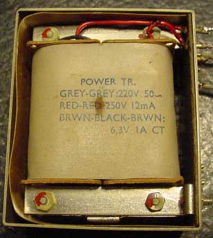
To get the right DC voltage for the Nixie tubes, I input 230 V AC into the 250 V winding.
After rectifying the old 220 winding I get 230 V DC unloaded, and 190 V DC loaded with 6 mA,
that is my nominal high voltage load, 1mA for each digit.
The old 6.3 Volt vinding now gives 5.5 V AC, so I am rectifying it with Schottky diodes to get max voltage out.
A low drop regulator is used to make the 5.0 V DC, max 10 mA needed.
Made June 2002.
This clock was made back in the good old days using homemade PCB,
After this clock was constructed, we made some nice prof PCB for sale.


The proffecional made PCB version 1.04, the powersupply and the clock board
This PCB and parts was sold via www.nixieclocks.de from 2003 to 2004.
in 2005 a brand new PCB and new super software will be released..
More about Nixie http://groups.yahoo.com/group/NEONIXIE-L/ This Best Nixie Clock kit for sale Claus Urbach
Free counter.digits.com